|
Overview
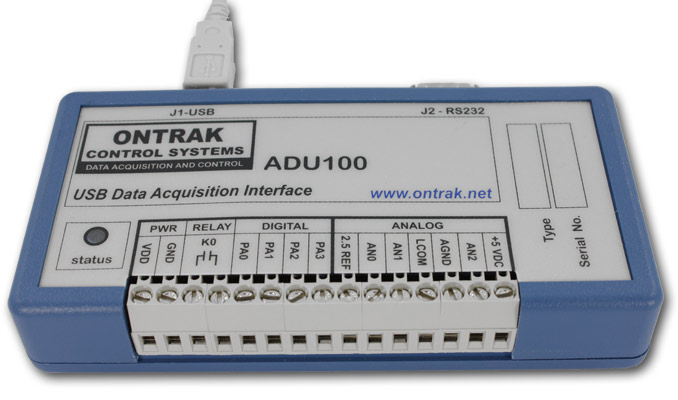
The ADU100 features 3, ISOLATED 16-bit analog inputs, 4 digital I/O lines, one 5 AMP
relay contact output, four 16 bit event counters, and an auxiliary RS232 port. Two of the
analog input lines can be programmed in 20mV to +/-2.5V ranges via an internal PGA. The
third analog input is a high-level input with programmable ranges of 0-5, +/-5, 0-10, and
+/-10 VDC. Two reference outputs are available ( 2.5000V and 5.00V ) to allow direct
connection of strain gauge type sensors.
Analog Connections:
The ADU100 features 3, ISOLATED 16-bit analog inputs Labeled AN0, AN1 and AN2.
AN0 and AN1 are low level inputs that can be used as two
single-ended inputs or as a single differential input for use with strain gauges or other
bridge type transducers.
 FIG 1:
Single-Ended Inputs FIG 1:
Single-Ended Inputs
Figure 1 shows the basic connections for single ended inputs. Note
that LCOM must be connected to AGND for single ended , unipolar inputs.
Single ended voltages can also be connected between AN2 and AGND. LCOM has no
function in regards to the use of AN2, the high level voltage input.
 FIG 2:
Potentiometer Connection FIG 2:
Potentiometer Connection
The reference outputs can provide bias currents to allow the direct
connection of potentiometers to the ADU100. Figure 2 shows how a potentiometer can be
connected to the low-level inputs using the 2.5V reference output. The high level input
will also accept potentiometer connections using the 5.00V output to bias the
potentiometer.
 FIG 3:
Bridge Connection ( 2.5V) FIG 3:
Bridge Connection ( 2.5V)
Figure 3 shows the basic bridge connection to the ADU100. Note that
bridge excitation can be provided by the ADU100 so that no external supply is required.
In this example, the bridge excitation is 2.500V and provides the lowest noise
measurement because the same voltage is used as the reference for the internal A/D
converter.
 FIG 4:
Bridge Connection ( 5V ) FIG 4:
Bridge Connection ( 5V )
Figure 4 shows an alternate method of connection bridge transducers
where the 5.00V output is used for excitation of a strain gauge transducer.
 FIG 5:
4-20mA Current Input FIG 5:
4-20mA Current Input
Standard current inputs can be connected to the ADU100 using
appropriate current loop termination resistors. In Figure 5, a 4-20mA current loop is
terminated with a 125 ohm resistor which effectively converts the current to a 0.5- 2.5
Volt signal. A second resistor could be used with a second current loop and connected to
AN0 in the same configuration.
 FIG 6:
4-20mA Current Input (2) FIG 6:
4-20mA Current Input (2)
The high level input AN2 can also accept current loop signals using
a 250 ohm termination resistor. This converts the current to a standard 1-5V signal which
can be read by the A/D converter. Both Figures 5 and 6 demonstrate how the ADU100 USB Data
Acquisition Interface can be used as a low cost isolated Current loop to USB ( I/USB)
converter.
IMPORTANT: Bipolar input voltages can be connected
to AN2 using AGND as the reference for the input. Special considerations must be taken
when using bi-polar inputs with AN0 and AN1 as these are pseudo-bipolar inputs that use
LCOM as the refererence for both inputs. When bi-polar inputs are to be used with AN0
and/or AN1, NO CONNECTION can be made to AGND, AN2, or either of the 2.5V or 5V reference
outputs. Figure 7 shows how bi-polar inputs are connected to AN0 and AN1.
FIG 7: Bi-Polar Inputs Connections to AN0 and AN1
Digital I/O Connections:
The ADU100 features a 4-bit digital I/O
port that can be configured in any combination of inputs or outputs. When configured
as outputs, the lines can sink or source up to 20mA per pin. This allows the direct
connection of low-current reed relays or LED's as shown in Figure 8.
 FIG 8:
Driving LED's FIG 8:
Driving LED's
The digital I/O lines also feature programmable pull-up resistors to
allow the connection of external contact input devices such as pushbuttons or PLC
contacts. Figure 9 shows how these pull-up resistors can be used. Contact input devices
are simply connected between the appropriate input and the GND pin.
 FIG 9:
Contact Inputs FIG 9:
Contact Inputs
Relay Connections:
The ADU100 features a relay output rated as
5 amps AC or DC. This allows the connection of external loads such as indicator lamps,
solenoids, small heaters, or other control related loads. Figure 10 shows the
connections required for a 24V indicator.
 FIG 10:
Contact Output FIG 10:
Contact Output
View the complete ADU100 data sheet HERE.
|