|
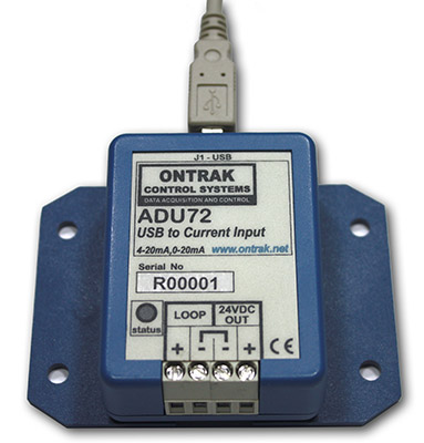
ADU72 USB to Current Input Interface (
4-20mA, 0-20mA Receiver )
The ADU72 USB to Current Input interface enables
measurement of 4-20mA and 0-20mA signals from standard process
transmitters via a single USB connection. The ADU72 internally generated 24VDC loop supply eliminates the need for an external loop power supply. This low-cost USB to Current
Input Interface is easy to use with VB, and Visual C++ or .NET via standard HID drivers included with Windows 98,2000,XP,7,8,10. A mini-driver ( DLL )* is also provided allowing control using standard ASCII commands using familiar readfile , writefile commands. The ADU72 includes a 10' USB cable and is available in a flange mount enclosure with a DIN rail mount option.
Connecting external devices to the ADU72 is
relatively simple, however, caution must be taken when
making connections to the internal 24VDC loop power
supply.
When using an external loop power supply, no connection
should be made to the "+" of the ADU72
24VDC OUT terminals.
1. Connecting the
ADU72 to 4-20mA Two-wire process transmitters.
Figure 1 shows the connections required to interface
to a two-wire process transmitter using the ADU72
internal 24V supply to power the loop. The two
connections shown are all that is required.
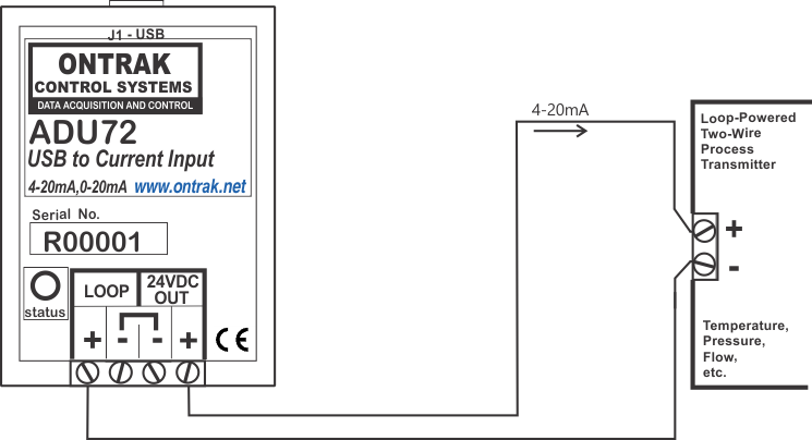
Figure1: ADU72 connections to a
loop-powered, two-wire, process transmitter.
If desired, an external loop power supply can be used
with loop-powered process transmitters. Connections are as shown in Figure 2.
When using an external loop power supply, no connections
should be made to either of the ADU72
24VDC OUT terminals.
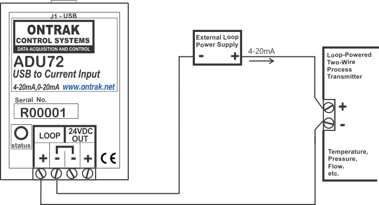
Figure 2: ADU72 connections a two-wire
transmitter using an external loop power supply.
2. Connecting the
ADU72 to 4-20mA Three-wire process transmitters.
The ADU72 is capable of providing 24VDC at 35mA to
power three wire process transmitters that operate on
35mA @ 24VDC or less. Figure 3 shows the proper
connections for this configuration.
CAUTION:
Do not use this configuration if the three-wire process
transmitter requires more than 35mA of supply current.
Use external supply as shown in Figure 4.
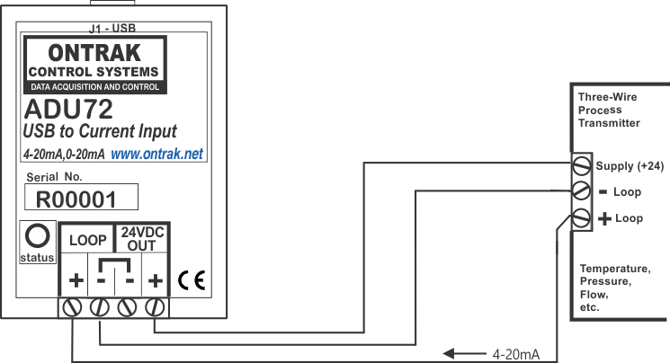
Figure 3 : ADU72 connections to a
three-wire process tranmitter that operates on 35mA or
less of supply current.
Figure 4 illustrates the proper connections to a
three-wire process transmitter using an external power
supply. This configuration is required if the
process transmitter requires more than 35mA of supply
current. CAUTION:
Make no connection to the ADU72 24VDC OUT
"+" terminal in this configuration.
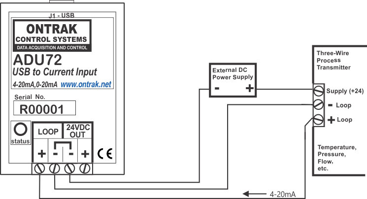
Figure 4 : ADU72 connections to a
three-wire process tranmitter using an external loop
power supply.
3. Connecting the ADU72 to
4-20mA Four-wire process transmitters.
The ADU72 is capable of
providing 24VDC at 35mA to power four- wire process
transmitters that operate on 35mA @ 24VDC or less.
Figure 5 shows the proper connections for this
configuration.
CAUTION:
Do not use this configuration if the four-wire process
transmitter requires more than 35mA of supply current.
Use external supply as shown in Figure 6.
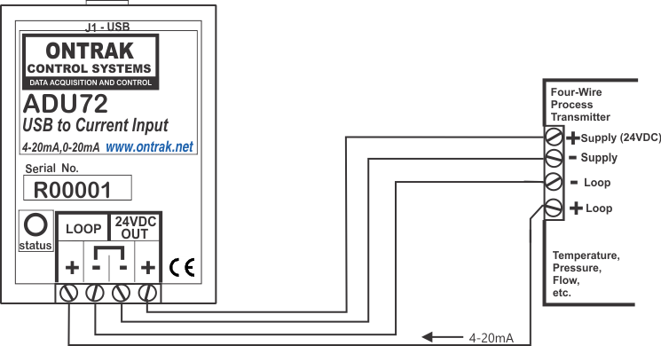
Figure 5 : ADU72 connections to a
four-wire process tranmitter that operates on 35mA or
less of supply current..
Figure 6 illustrates the proper connections to a
four-wire process transmitter using an external power
supply. This configuration is required if the
process transmitter requires more than 35mA of supply
current. CAUTION:
Make no connection to the ADU72 24VDC OUT "+"
terminal in this configuration.
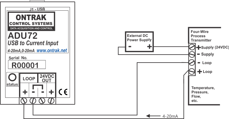
Figure 6 : ADU72 connections to a
four-wire process tranmitter using an external
power supply.
Back to Products Page |