|
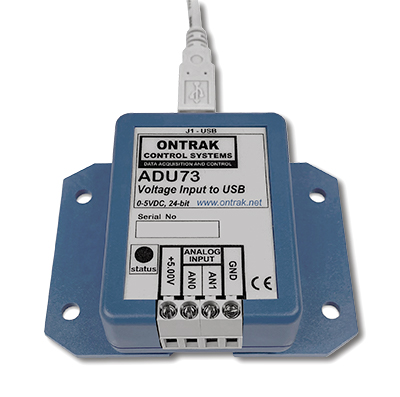
ADU73 Voltage Input to USB Interface (Dual 0-5VDC)
The ADU73 Voltage Input to USB Interface enables
measurement of two 0-5VDC analog inputs, with 24-bit resolution, using a USB connection.
The 5.000V reference output enables ratio-metric measurements of resistive
sensors, including string pots and linear potentiometers, providing exceptional low noise 24-bit measurements. This low-cost USB
Voltage Input to USB Interface is easy to use with VB, and Visual C++ or .NET via standard HID drivers included with Windows 98,2000,XP,7,8,10,11. A mini-driver ( DLL )* is also provided allowing control using standard ASCII commands using familiar readfile, writefile commands. The ADU73 includes a 10' USB cable and is available in a flange mount enclosure with a DIN rail mount option.
Connecting external devices to the ADU73 is
relatively simple, however, care should be taken when
making connections to avoid measurement errors, or
damage to the ADU73.
The maximum current draw from the +5.00V reference
output should not exceed 20mA.
1. Connecting the
ADU73 to resistive potentiometers.
Figure 1 shows the connections required to interface
the ADU73 to resistive position sensing potentiometers,
including linear potentiometers and string pots (draw
string potentiometer). The
potentiometers are biased using the +5.00V reference
output to enable ratio-metric measurements. Minimum
recommended potentiometer resistance 1K ohm. Do not draw
more than 20mA in total from the +5.00V reference
output.
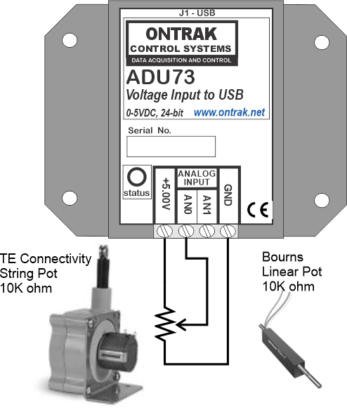
Figure1: ADU73 connections to
TE Connectivity string pot or
Bourns linear motion resistive
potentiometers.
2. Connecting the
ADU73 to active sensors.
Active sensors can also be connected to the ADU73
with the only limitation being that a maximum of 20mA
can be drawn from the +5.00VDC reference output to power
the sensor. Figure 2 shows the connections to an
MPXV5050DP pressure sensor from NXP. The MPXV5050DP
draws only 7mA @ 5 VDC and so two sensors can be
connected safely.
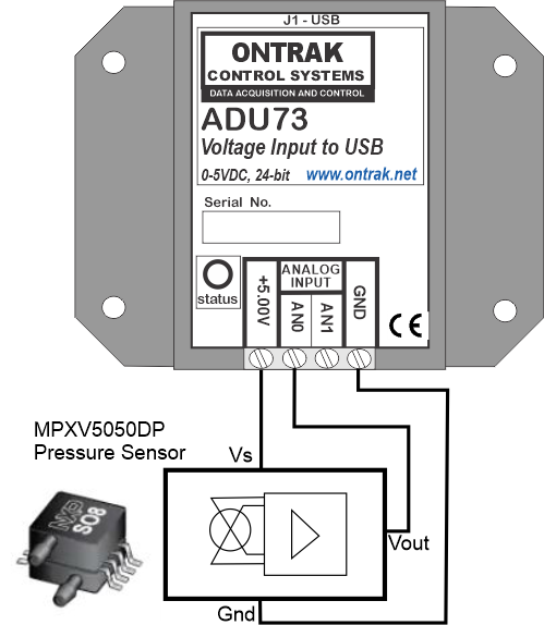
Figure 2: ADU73 connections to an
active sensor (MPXV5050DP
Pressure Sensor).
3. Connecting the
ADU73 to thermistors.
The ADU73 can be connected to thermistors using an
external bias resistor. The external bias resistor
resistance depends on both thermistor resistance, and
the application requirements, and should be selected to
ensure a maximum of 20mA is drawn from the +5.00V
reference output. Up to two thermistors can be
connected to the ADU73.
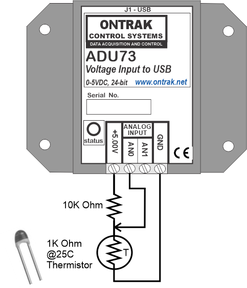
Figure 3 : ADU73 connections to a
thermistor.
4. Connecting the
ADU73 to external voltage sources.
The ADU73 can be connected to external voltage
sources of up to 5VDC, including standard
instrumentation 1-5VDC signals. Note that in this
configuration, the ADU73 is operating in absolute
voltage measurement mode. CAUTION: No
connection should be made to the +5.00V reference output
when connecting external voltages.
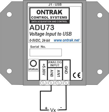
Figure 4 : ADU73 connection to an
external voltage source.
Back to Products Page |