|
 View the ADU series of USB based Data Acquisition Products
Introduction
Communicating with USB devices in LabView, or
virtually any application software, involves a few
simple steps. Unlike RS232 based devices which are
connected to physical COM ports, USB devices are
assigned a logical handle
by operating systems when they are first plugged in.
This process is known as enumeration.
Once a USB device has been
enumerated, it is ready for use by the host computer
software. For the host application software to
communicate with the USB device, it must first obtain
the handle assigned to the USB device during the
enumeration process. The handle can be obtained using an
open function along with
some specific information about the USB device.
Information that can be used to obtain a handle to a USB
device include, serial number,
product ID, or vendor
ID. Once the handle is obtained, it is used to allow the
application to read and write information, to and from,
the USB device. Once the application has finished
with all communication with the USB device, the handle
is closed. The handle is generally closed when the
application terminates.
The AduHid DLL provides all the
functions to open a handle, read and write data, and
close the handle of ADU USB devices. The ADUHID dll can
be used directly from a LabView application. The
following example VI demonstrates how to OPEN a handle,
SEND commands, RECEIVE data, and finally, CLOSE the
handle to the ADU USB device when the program is stopped
or closed.
The sample program below is a
rendition of our AduHidTest program demonstrating the
proper method to utilize the functions within the
ADUHID dll to communicate with ADU, USB based data
acquisition products. If you have never used ADU, USB
based devices, it is recommended that you first download
and run the AduHidTest software to become familiar with
the process of communication with USB devices in
application software. A tutorial and download link is
located HERE.
This basic example VI demonstrates manual communication
with an ADU, USB device. Note that the VI is for a
single connected ADU device only as it opens the first
enumerated ADU device it encounters.
Lets have a look at the front panel.....
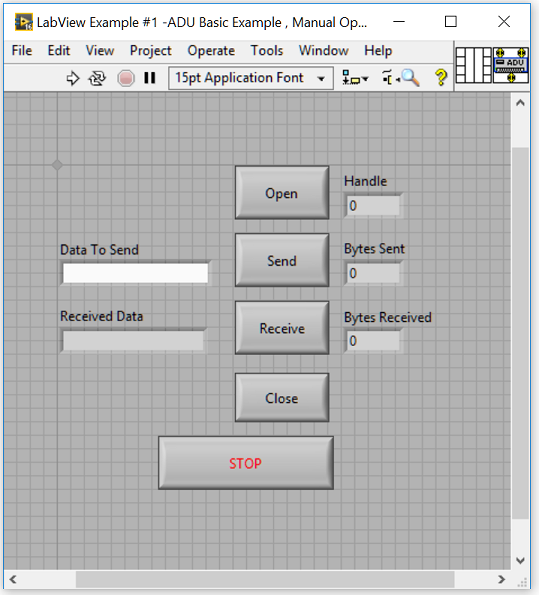
Figure 1. LabView Example # 1 ADU Basic Example - Manual
Operation - Front Panel
The front panel controls are very similar to the
AduHidTest application and include a button to
Open a handle to the connected ADU device, a
button to Send data contained in the
Data To Send string control, a button
to Receive data from the ADU and
display it in the Received Data string
indicator, and finally, a button to Close
the Handle to the ADU device. Numeric indicators
displaying Handle, Bytes Sent and Bytes Received are
also visible to aid in understanding the operation of the
VI. A STOP
button is used to stop the VI, and close the open
handle, if any.
Lets have a look at the block diagram for the VI.
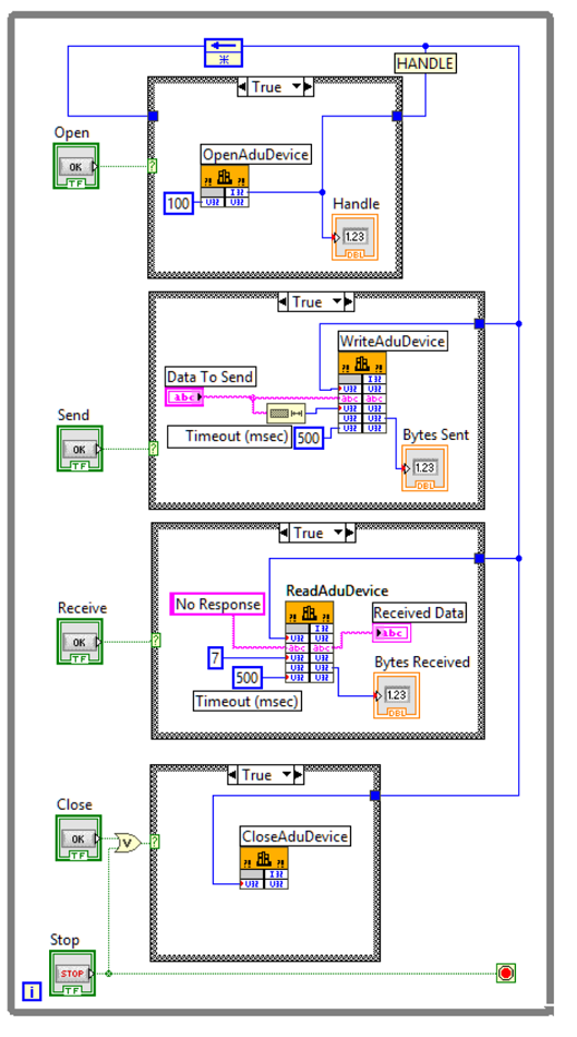
Figure 2: LabView Example # 1 ADU Basic Example - Manual
Operation - Block Diagram
The block diagram is made up of four case
structures to facilitate manual communications
with ADU, USB devices. Each case structure
contains a specific call library function
to access related functions contained in the
AduHid.dll. Note that for proper operation of the
VI, the dll should be located in the same directory as
the VI.
The OPEN function.
The first case structure is used to obtain a handle to
the connected ADU device and place it on the wire
labeled HANDLE. Note that a feedback node is used
in the case structure to hold the handle value on the
wire when the Open button is released. It is wired
straight through in the False state as seen in Figure 3.
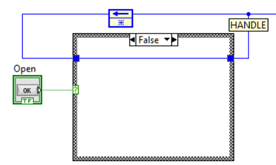
Figure 3: Feedback Node wiring in
Open Case Structure in False state.
When the Open button is pressed, the Windows assigned
handle will be present on the wire labeled HANDLE. This
handle is then used by the Send and Receive functions to
communicate with the connected ADU device. In this
example VI, the handle is selected for the first
available ADU device found in the Windows registry with
the Vendor ID for Ontrak Control Systems.
Additional functions are available to open an ADU device
by Serial Number or Product ID
for use in multiple ADU applications. See the ADU
Windows SDK for details
HERE.
IMPORTANT NOTES - Using
Windows USB Handles
1. Only open one handle to any particular USB device
and ensure it is closed when the program terminates.
Opening multiple handles, without first closing unused
handles, will cause a handle leak in the
Windows operating system. If too many handles are
opened, Windows will disable further USB communications.
2 The handle should be opened when the program
starts, or communication with the ADU device commences.
3. The handle should be closed only when the program
is stopped, or terminates.
4. DO NOT open and close the handle every time
communications with the USB device is required. The
handle should remain open until the program is stopped
or terminates. This is particularly important in newer
versions of Windows with USB Selective Suspend
enabled as, if no handle is open to the USB device,
Windows will suspend the device causing a loss of power
for the output stage on some ADU devices. ADU devices
that will lose output states on loss of power ( suspend
) include, the entire ADU70 series, ADU228, ADU258,
ADU222, and the ADU252. ADU devices that maintain
output states in suspend mode include the ADU100,
ADU200, ADU208 and ADU218.
The SEND Function.
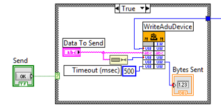
Figure 4: The Send function.
When the Send button is activated, text typed into
the Data To Send string control is sent
to the ADU device provided a valid handle has been
obtained. The text string should be a valid ADU command
for the connected device. Consult your ADU User Manual
for a list of commands available. The WriteAduDevice function requires the text
string, along with the number of bytes in the text
string it is sending. The number of bytes in the text
string is obtained using a string length
control and connected to the appropriate node of the
function. The only additional requirement is a timout
value which was set to 500ms using a numeric
constant.
The RECEIVE function.
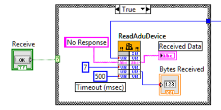
Figure 5: The Receive function.
If the command sent to the ADU device is a responsive
command, or one which returns data, that data can be
retrieved using the ReadAduDevice function. When the
Receive button is activated, any data the ADU returned
is transferred to the Received Data
string indicator. The "No Response" fixed string
is a placeholder that is passed to the Received
Data string indicator if no data was returned
by the ADU device. The numeric constant "7" is a dll
input indicating how many bytes are to be received.
Note that the number of bytes received will either be 7
for low-speed ADU devices, or 63 for full-speed ADU
devices. The only additional requirement is a timout
value which was set to 500 ms using a numeric
constant.
The CLOSE function.
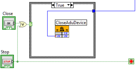
Figure 6: The Close function.
The CloseAduDevice function should be called when the
program is terminated, or, if desired, the user manually
closes the handle to the USB device by activating the
Close button. Note that the program STOP button is OR'ed
with the Close button so that either
can close the handle to the ADU device.
Final Notes....
This VI provides basic functionality only. Many
additional functions are available through the AduHid
DLL including , error codes, device lists, etc.
Future LabView examples will demonstrate these
additional functions including ADU device specific
examples.
DOWNLOAD LabView Example
#1 VI including AduHid DLL ( 2016 and 2009
versions)
|