|
LM335 Temperature Measurement
1. Introduction
The following application demonstrates how LabVIEW can be used
with ADR interfaces, or any ASCII based serial data acquisition and control interface. The
application is a simple temperature measurement and plot using
an ADR112 and an LM335 solid-state temperature sensor. It is assumed the
user has a basic knowledge of LabVIEW, however, no prior experience with LabVIEW is
required as long as the user manual is available to help with the generic tasks. Figure 1
shows our final operating panel for the application in operation. The panel allows
adjustment of the sample rate via a rotary knob, and displays temperature vs. time in a
graph format. A digital reading of present temperature is also provided. The hardware
consists of an ADR112 connected to com2, interfaced to an LM335 temperature sensor
connected to AN0.
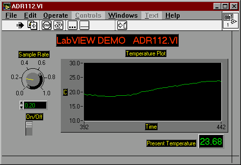
Figure 1: Final Operating Panel
2. Lets Get Started.
Start labview, and an blank panel will appear called untitled.VI.
Save the VI as a file called "START". We will now place various controls and
indicators on the blank panel that will become the applications operating controls and
indicators. Using the CONTROLS menu, place on the following on the panel;
A waveform chart from CONTROLS/ARRAY AND GRAPH/WAVEFORM CHART
A numeric knob from CONTROLS/NUMERIC/KNOB
A vertical switch from CONTROLS/BOOLEAN/VERTICAL SWITCH
A numeric indicator from CONTROLS/NUMERIC/DIGITAL INDICATOR.
Arrange the items as shown in Figure 2 using the pointer to add
labels by right clicking on each item and typing it in. Change the scale on the waveform
chart vertical axis to 0 to 4095 using the hand icon.
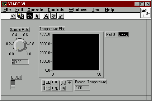
Figure 2 : Initial Panel Layout
Use the hot key, CTRL-F to show the control diagram. Arrange the
items to the positions shown in Figure 3.
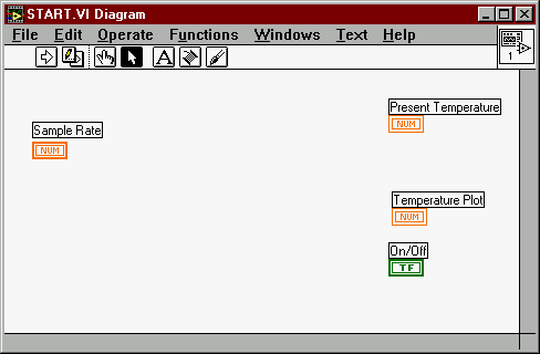
Figure 3 : Initial Control Diagram
3. Building the Program
Before starting to build the program we must understand what
we want the program to do for us. We should have a basic knowledge the application
hardware and desired operating parameters. This application will require the software to
send an "RD0" command ( followed by a carriage return ) to the ADR112, causing
it to respond with a four digit integer number from 0000 to 4095 representing the
temperature data in 12-bit format. The data must then be scaled and displayed on the front
panel in degrees Celsius in a digital display and in a waveform chart showing temperature
history. The basic program will repeat this operation at a rate determined by our
adjustable sample rate knob. For this we will start by selecting a WHILE LOOP using
FUNCTIONS/STUCTSANDCONSTANTS/WHILELOOP. position the loop as shown in
Figure 4.
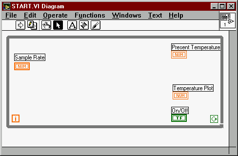
Figure 4 : Adding the While Loop
We will now add the components required to have the loop execute at
an adjustable interval by adding a few more components. Add the following three
components;
A wait function timer from FUNCTIONS/TIMEANDDIALOG/WAIT
A multiply function from FUNCTIONS/ARITHMATIC/MULTIPLY
A numeric constant from FUNCTIONS/STUCTSANDCONSTANTS/NUMERICCONSTANT
Position the items as shown in Figure 5 and wire them as shown using
the wiring tool. The timer will now delay repeated execution of the loop by 1000 times the
setting of the sample rate knob on the front panel.( in ms). If the knob is set at
one, the sample rate will be 1 second ( 1000 X 1=1000ms ), if the knob is set at 0.5 the
sample rate will be 0.5 seconds ( 1000 X 0.5 = 500ms), etc. The on/off slide switch
is wired as shown to enable or disable the loop from running. It will serve as a simple
enable/stop function on the front panel.
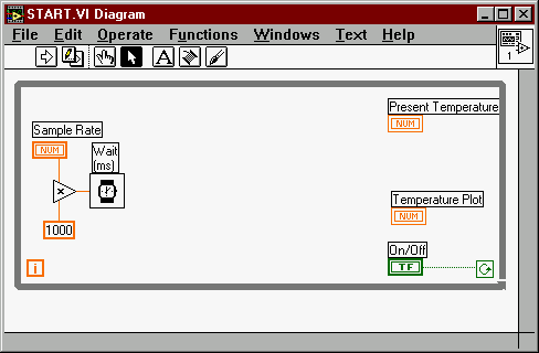
Figure 5 : The Delay
4. The Sequencer
The software in the loop must now be set up to send and receive
ASCII data to the ADR112 via Com2. This is accomplished by using a sequencer and a number
of serial port functions provided by LabVIEW. The sequence, as the name implies,
allows the execution of code in a specific sequence similar to that of a PLC. The
sequencer is a series of frames that code is placed into, that determines the actual
execution sequence of the code. Add a sequencer to the control diagram using
FUNCTIONS/STUCTSANDCONSTANTS/SEQUENCER. position the sequencer as shown in figure 6.
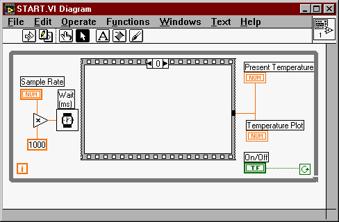
Figure 6 : The Sequencer
5. Writing Data to the Serial Port
The first frame will contain the actual serial write function. Also
added in this step is the serial port initialize function. Place the serial write function
inside frame 0 by selecting it from FUNCTION/SERIAL/SERIALWRITE. Place the serial
initialize function outside the while loop as shown in Figure 7 using
FUNCTION/SERIAL/SERIALINITIALIZE. Use a numeric constant to set initialize the
port to Com2 ( port 1) and set the port for the write operation by wiring as shown. A
command string of "RD0" must be sent in the write operation and it must be
followed by a carriage return for the ADR112 to respond. This is done by selecting a
string constant using FUNCTIONS/STUCTSANDCONSTANTS/STRINGCONSTANT. Enter RD0 followed by a
carriage return as the string constant and wire as shown in Figure 7.
IMPORTANT; The default
termination character for an ASCII string in LabVIEW is a linefeed character which will
not cause the ADR112 to return data. The linefeed must be changed manually to a carriage
return. This is done by right clicking on the data and selecting " \ CODES
DISPLAY". When this is done, "RD0\n" will be the displayed string data. Use
the text icon to change the \n to \r ( carriage return ). If successful, the string will
as be shown as in Figure 7 with the " \ CODES DISPLAY" function enabled.
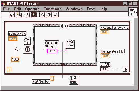
Figure 7 : Serial Write Function
6. Adding a Step
A second step is to be added to the sequencer where the serial read
function will be placed. this is done by right clicking on the sequencer frame
indicator and selecting " ADD FRAME AFTER". The sequencer will appear as shown
in Figure 8.
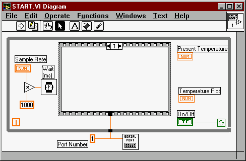
Figure 8 : Adding a Step
7. Reading and Displaying Data
The data returned from the ADR112 will be read using a "serial
read with timeout" vi. This vi is included with LabVIEW in the samples directory.
Place it in the frame along with a "Format and Strip" function from
FUNCTION/STRING/FORMATANDSTRIP. Wire as shown in Figure 9 including, a numeric constant of
5 for number of bytes to receive ( 4 plus CR ), and a string constant of "%d" to
identify the incoming data as integer format. Wire the output of the " Format and
Strip" function to both the " Present Temperature" display and the "
Temperature Plot "
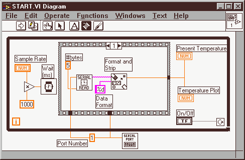
Figure 9 : Reading and Formatting Data
8. First Run Through
This would be a good time to test the program. Connect a
potentiometer to AN0 on the ADR112 and run the VI from the Panel Window. Vary the pot and
the display should look something like Figure 10. Vary the sample rate to become familiar
with its operation. Do not forget to click on the ON/OFF switch to enable operation.
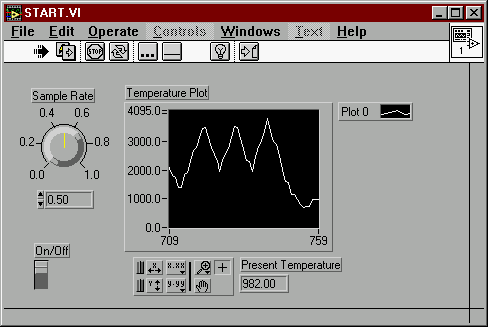
Figure 10 : First Run Through.
9. Finalizing Application
Finalizing the application involves converting the ASCII data to
Celsius. This is done with a one arithmetic subtraction and one division function
added to the second step in the sequencer as shown in Figure 11. These functions are
necessary to convert the 12-bit data to Celsius and are explained in the application note
"Using the LM335 Temperature Sensor"
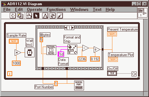
Figure 11 : The Final Code
The display can then be customized to give the VI a more pleasing
appearance. See your user manual for the various customizing options. The scale of the
graph can also set using the hand icon to whatever range is to be measured in the
application. Our final version was saved as "ADR112.VI" as appears as in Figure
12.

Figure 12 : Final Panel
10. Where Do We Go From Here?
This was a simple application using only one analog input port
of the ADR112 interface. Additional graphs or use of the digital ports for alarms
can be facilitated simply by adding steps to the sequencer with additional write and read
operations. All of the functions found on ADR interfaces including,
counters, PWM, digital I/O, analog outputs, interuppts and stepper indexers
can be utilized with LabVIEW. Programs can be as complex or as simple as the application
requires. The people at National Instruments have done an outstanding job developing
LabVIEW and it is easy to see why it has become so popular.
Note: The VI used in this example can be downloaded
in zip format using the following link;
ADR112.VI in ZIP Format (13KB)
Ordering LabVIEW ( Students and Educators)
LabVIEW student edition is available for around $100.00 direct from
the publisher. This graphical programming software is designed for scientists and
engineers who automate laboratories or take industrial measurements. When coupled with the
low-cost ADR interfaces, an affordable data acquisition and
control hardware/software solution is achieved.
 LabVIEW
Student Edition, Author, Lisa K. Wells, National Instruments LabVIEW
Student Edition, Author, Lisa K. Wells, National Instruments
Publisher: Prentice
Hall
ORDERING USA 1-800-643-5506 CANADA 1-800-567-3800 (
VISA,MC,AMEX)
ISBN 0-13-210709-0 Macintosh Version
ISBN 0-13-210691-4 Windows Version
Ordering LabVIEW ( Non-Educational)
Contact National Instruments
for pricing and delivery of full license versions.
Back to Programming Page |